Dimension tables and information
Here you can find tables and technical information about dimensions , materials and standards
Dimension table DIN
| Dimension | DIN Serie 1 / Reihe 1 |
DIN Serie 2 / Reihe 2 |
DIN Serie 3 / Reihe 3 |
Old Expired DIN |
|---|---|---|---|---|
| DN 10 | 12.0×1.0 | 13.0×1.5 | 14.0×2.0 | 12.0×1.5 |
| DN 15 | 18.0×1.0 | 19.0×1.5 | 20.0×2.0 | 18.0×1.5 |
| DN 20 | 22.0×1.0 | 23.0×1.5 | 24.0×2.0 | 22.0×1.5 |
| DN 25 | 28.0×1.0 | 29.0×1.5 | 30.0×2.0 | 28.0×1.5 |
| DN 32 | 34.0×1.0 | 35.0×1.5 | 36.0×2.0 | 34.0×1.5 |
| DN 40 | 40.0×1.0 | 41.0×1.5 | 42.0×2.0 | 40.0×1.5 |
| DN 50 | 52.0×1.0 | 53.0×1.5 | 54.0×2.0 | 52.0×1.5 |
| DN 65 | 70.0×2.0 | 70.0×2.0 | 70.0×2.0 | – |
| DN 80 | 85.0×2.0 | 85.0×2.0 | 85.0×2.0 | – |
| DN 100 | 104.0×2.0 | 104.0×2.0 | 104.0×2.0 | – |
Dimension table all standards
| DN | SMS 3008 |
DIN 11850 serie 2 |
ISO 1127 serie 1 |
ANSI sch 5 |
Metrisk MM/SSG |
OD SWG/BWG |
BPE |
|---|---|---|---|---|---|---|---|
| 6 | 6.0×1.0 | ||||||
| 8 | 13.5×1.6 | 8.0×1.0 | 6.35×0.89 | 6.35×0.89 | |||
| 10.0×1.0 | |||||||
| 10 | 13.5×1.5 | 17.2×1.6 | 17.20×1.65 | 12.0×1.0 | 9.53×0.89 | 9.53×0.89 | |
| 14.0×1.0 | |||||||
| 15 | 12.0×1.0 | 19.0×1.5 | 21.3×1.6 | 21.34×1.65 | 16.0×1.0 | 12.70×1.24 | 12.70×1.65 |
| 18.0×1.5 | 12.70×1.65 | ||||||
| 20.0×1.5 | |||||||
| 20.0×2.0 | |||||||
| 20 | 18.0×1.0 | 23.0×1.5 | 26.9×2.0 | 26.67×1.65 | 25.0×1.5 | 19.05×1.24 | 19.05×1.65 |
| 25.0×2.0 | 19.05×1.65 | ||||||
| 25 | 25.0×1.2 | 29.0×1.5 | 33.7×2.0 | 33.40×1.65 | 30.0×1.5 | 25.40×1.65 | 25.40×1.65 |
| 30.0×2.0 | |||||||
| 32 | 32.0×1.2 | 35.0×1.5 | 42.4×2.0 | 42.16×1.65 | 38.0×2.0 | ||
| 40 | 38.0×1.2 | 41.0×1.5 | 48.3×2.0 | 48.26×1.65 | 44.5×2.0 | 38.10×1.65 | 38.10×1.65 |
| 50 | 51.0×1.2 | 53.0×1.5 | 60.3×2.0 | 60.32×1.65 | 54.0×2.0 | 50.80×1.65 | 50.80×1.65 |
| 65 | 63.5×1.6 | 70.0×2.0 | 76.1×2.0 | 73.03×2.11 | 69.0×2.0 | 63.50×1.65 | 63.50×1.65 |
| 80 | 76.1×1.6 | 85.0×2.0 | 88.9×2.0 | 88.90×2.11 | 84.0×2.0 | 76.20×1.65 | 76.20×1.65 |
| 100 | 101.6×2.0 | 104.0×2.0 | 114.3×2.0 | 114.3×2.11 | 104.0×2.0 | 101.6×2.11 | 101.6×2.11 |
| 125 | 129.0×2.0 | 139.7×2.6 | 141.30×2.77 | 129.0×2.0 | |||
| 150 | 154.0×2.0 | 168.3×2.6 | 168.28×2.77 | 154.0×2.0 | 152.40×2.77 | 152.40×2.77 | |
| 200 | 204.0×2.0 | 219.1×2.6 | 219.08×2.77 | 204.0×2.0 | 203.20×2.77 | 203.20×2.77 | |
| 250 | 273.0×2.6 | 273.05×3.40 | 254.0×2.0 | ||||
| 300 | 323.9×2.6 | 323.85×3.96 | 304.0×3.0 |
Surface finish table DIN 11864
| Hygiene class | Quality | Material | Internal Ra µm |
Over weld Ra µm |
Sveflows term |
|---|---|---|---|---|---|
| H2 | Seamless / welded pipes | 1.4404 / 1.4435 | <0.8 | <1.6 | – |
| H3 | Seamless / welded pipes | 1.4404 | <0.8 | <0.8 | S |
| H3 | Seamless / welded pipes | 1.4435 | <0.8 | <0.8 | W |
| HE3 | Seamless / welded pipes, electropolished | 1.4404 | <0.8 | <0.8 | X |
| HE3 | Seamless / welded pipes, electropolished | 1.4435 | <0.8 | <0.8 | WX |
| H4 | Seamless / welded pipes, internally gounded | 1.4404 | <0.4 | <0.4 | AQ |
| H4 | Seamless / welded pipes, internally gounded | 1.4435 | <0.4 | <0.4 | W/1 |
| HE4 | Seamless / welded pipes, internally gounded and electropolished | 1.4404 | <0.4 | <0.4 | AQX |
| HE4 | Seamless / welded pipes, internally gounded and electropolished | 1.4435 | <0.4 | <0.4 | WX/1 |
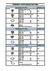
Overview connections DIN 11864
Dimension table ASME BPE
| Nominal size | Pipe Ø outside mm | Pipe Ø outside inch (tum) | Thickness mm | Thickness inch (tum) |
Clamp size |
|---|---|---|---|---|---|
| 1/4″ | 6.35 | 0.250 | 0.89 | 0.035 | 1 |
| 3/8″ | 9.53 | 0.375 | 0.89 | 0.035 | 1 |
| 1/2″ | 12.70 | 0.500 | 1.65 | 0.065 | 1 |
| 3/4″ | 19.05 | 0.750 | 1.65 | 0.065 | 1 |
| 1″ | 25.40 | 1.000 | 1.65 | 0.065 | 3 |
| 1 1/2″ | 38.10 | 1.500 | 1.65 | 0.065 | 3 |
| 2″ | 50.80 | 2.000 | 1.65 | 0.065 | 4 |
| 2 1/2″ | 63.50 | 2.500 | 1.65 | 0.065 | 5 |
| 3″ | 76.20 | 3.000 | 1.65 | 0.065 | 6 |
| 4″ | 101.60 | 4.000 | 2.11 | 0.083 | 8 |
| 6″ | 152.40 | 6.000 | 2.77 | 0.109 | 12 |
Surface finish table ASME BPE
| Parts | Internal surface | External surface | |||
|---|---|---|---|---|---|
| Sveflows surface kode |
ASME BPE kode | Ra max | Surface treatment | Surface treatment | |
| μ-in. | μm | ||||
| – | SF1 | 20 | 0.500 | Mechanically grounded | Untreated |
| AQ | SF1 | 20 | 0.500 | Mechanically grounded | Mechanically grounded 0.8 µm |
| – | SF2 | 25 | 0.625 | Mechanically grounded | Untreated |
| – | SF3 | 30 | 0.750 | Mechanically grounded | Untreated |
| – | SF4 | 15 | 0.375 | Mechanically grounded & electropolished | Untreated |
| AQX | SF4 | 15 | 0.375 | Mechanically grounded & electropolished | Mechanically grounded 0.8 µm |
| – | SF5 | 20 | 0.500 | Mechanically grounded & electropolished | Untreated |
| – | SF6 | 25 | 0.625 | Mechanically grounded & electropolished | Untreated |
Surface finish table ASME BPE
| Pipes | Internal surface | External surface | |||
|---|---|---|---|---|---|
| Sveflows surface kode |
ASME BPE kode | Ra max | Surface treatment | Surface tratment | |
| μ-in. | μm | ||||
| AQ | SF1 | 20 | 0.500 | Mechanically grounded | Mechanically grounded 0.8 µm |
| – | SF2 | 25 | 0.625 | Mechanically grounded | Mechanically grounded 0.8 µm |
| – | SF3 | 30 | 0.750 | Mechanically grounded | Mechanically grounded 0.8 µm |
| X | SF4 | 15 | 0.375 | Mechanically grounded & electropolished | Mechanically grounded 0.8 µm |
| – | SF5 | 20 | 0.500 | Electropolished | Mechanically grounded 0.8 µm |
| – | SF6 | 25 | 0.625 | Electropolished | Mechanically grounded 0.8 µm |
Surface finish according to ASME BPE specifications part SF, table SF-2
DT-table ASME BPE
| Item | Item number | New DT-number | Old DT-number |
|---|---|---|---|
| Tube | 0100-BPE… | DT-4-1 | DT-1 |
| Bend 90° with straight end | 1000-BPE… | DT-4.1.1-1 | DT-7 |
| Bend 90° with TC × 1 | 1021-BPE… | DT-4.1.1-2 | DT-12 |
| Bend 90° with TC × 2 | 1025-BPE… | DT-4.1.1-3 | DT-16 |
| Bend 45° | 1060-BPE… | DT-4.1.1-4 | DT-8 |
| Bend 45° with TC × 1 | 1061-BPE… | DT-4.1.1-5 | DT-13 |
| Bend 45° with TC × 2 | 1065-BPE… | DT-4.1.1-6 | DT-17 |
| U-bend 180° | 1005-BPE… | DT-4.1.1-7 | DT-23 |
| U-bend 180° with TC × 2 | 1005-BPE…/1 | DT-4.1.1-8 | DT-24 |
| Tee long | 1150-BPE… | DT-4.1.2-1 | DT-9 |
| Cross tee | 1180-BPE… | DT-4.1.2-1 | DT-9 |
| Tee short with TC × 1 | 1156-BPE… | DT-4.1.2-2 | DT-15 |
| Tee short with TC × 1 | 1156-BPE… | DT-4.1.2-2 | DT-15 |
| Tee short side with TC × 1 | 1153-BPE… | DT-4.1.2-3 | DT-25 |
| Tee long with TC × 3 | 1155-BPE… | DT-4.1.2-4 | DT-18 |
| Cross tee with TC × 4 | 1185-BPE… | DT-4.1.2-4 | DT-18 |
| Tee short with TC × 3 | 1157-BPE… | DT-4.1.2-5 | DT-27 |
| Tee long reduced | 1151-BPE… | DT-4.1.2-6 | DT-10 |
| Tee short reduced with TC × 1 | 1152-BPE… | DT-4.1.2-7 | DT-14 |
| Tee long reduced with TC × 3 | 1161-BPE… | DT-4.1.2-8 | DT-19 |
| Tee short reduced with TC × 3 | 1163-BPE… | DT-4.1.2-9 | DT-20 |
| Instrument Tee | 1158-BPE… | DT-4.1.2-10 | DT-28 |
| Instrument Tee with TC × 3 | 1159-BPE… | DT-4.1.2-11 | DT-29 |
| Reducer concentric | 1120-BPE…/1 | DT-4.1.3-1 | DT-11 |
| Reducer eccentric | 1130-BPE…/1 | DT-4.1.3-1 | DT-11 |
| Reducer concentric with TC × 1 | 1121-BPE…/1 | DT-4.1.3-2 | DT-26 |
| Reducer eccentric with TC × 1 | 1131-BPE…/1 | DT-4.1.3-2 | DT-26 |
| Reducer concentric with TC × 2 | 1125-BPE…/1 | DT-4.1.3-3 | DT-21 |
| Reducer eccentric with TC × 2 | 1135-BPE…/1 | DT-4.1.3-3 | DT-21 |
| Clamp ferrule | 0520-BPE… | DT-4.1.4-1 | DT-22 |
| Convex end cap | 0472-BPE… | DT-4.1.5-1 | DT-30 |
| Clamp end cap | 0560-BPE… | DT-4.1.5-2 | DT-31 |
Dimension table clampflanges
| Tum | ½-¾” | 10-20 | 1-1½” | 2″ | 2½” | 3″ | 3½” | 4″ | 4½” | 5″ | 5½” | 6″ | 6 5/8″ | 8″ | 8 5/8″ | 10″ | 10 5/8″ | 12″ | 12 5/8″ |
|---|---|---|---|---|---|---|---|---|---|---|---|---|---|---|---|---|---|---|---|
| Connec. | 12-18 | 20.0 | 25-38 | 51.0 | 63.5 | 76.0 | 89.0 | 101.6 | 115.0 | 125.0 | 140.0 | 150.0 | 170.0 | 200.0 | 220.0 | 250.0 | 270.0 | 300.0 | 370.0 |
| Flange | 25.4 | 34.0 | 50.5 | 64.0 | 77.5 | 91.0 | 106.0 | 119.0 | 130.0 | 144.4 | 155.0 | 167.0 | 183.0 | 217.4 | 233.5 | 268.0 | 286.1 | 319.0 | 338.0 |
| Size | 1 | 2 | 3 | 4 | 5 | 6 | 7 | 8 | 9 | 10 | 11 | 12 | 13 | 14 | 15 | 16 | 17 | 18 | 19 |
Formula for pipeweight
Pipe diameter – material thickness × material thickness × 25.04 / 1000 = vikt i kg
Exemple sms-pipe size 25×1.2mm: 25.0-1.2×1.2×25.04/1000=0.72kg
Dimension table in size order
| DN | Tum | Dimension | Standard |
|---|---|---|---|
| 6.00×1.00 | MM | ||
| 8 | 0.25″ | 6.35×0.89 | OD |
| 8 | 0.25″ | 6.35×0.89 | BPE |
| 8.00×1.00 | MM | ||
| 10 | 3/8″ | 9.53×0.89 | OD |
| 10 | 3/8″ | 9.53×0.89 | BPE |
| 10.00×1.0 | MM | ||
| 10 | 12.00×1.0 | MM | |
| 10 | 12.00×1.5 | DIN | |
| 15 | 0.5″ | 12.70×1.24 | OD |
| 15 | 0.5″ | 12.70×1.65 | OD |
| 15 | 0.5″ | 12.70×1.65 | BPE |
| 10 | 13.00×1.50 | DIN 2 | |
| 8 | 0.25″ | 13.50×1.60 | ISO |
| 14.00×1.00 | MM | ||
| 16.00×1.00 | MM | ||
| 10 | 3/8″ | 17.20×1.60 | ISO |
| 10 | 3/8″ | 17.20×1.65 | ANSI |
| 20 | 18.00×1.00 | SMS | |
| 15 | 18.00×1.50 | MM/DIN | |
| 15 | 19.00×1.50 | DIN 2 | |
| 20 | 0.75″ | 19.05×1.24 | OD |
| 20 | 0.75″ | 19.05×1.65 | OD |
| 20 | 0.75″ | 19.05×1.65 | BPE |
| 15 | 20.00×1.50 | MM | |
| 15 | 20.00×2.00 | MM | |
| 15 | 0.5″ | 21.30×1.60 | ISO |
| 15 | 0.5″ | 21.34×1.65 | ANSI |
| 20 | 22.00×1.50 | DIN | |
| 20 | 23.00×1.50 | DIN 2 | |
| 25 | 25.00×1.20 | SMS | |
| 20 | 25.00×1.50 | MM | |
| 20 | 25.00×2.00 | MM | |
| 25 | 1.0″ | 25.40×1.65 | OD |
| 25 | 1.0″ | 25.40×1.65 | BPE |
| 20 | 0.75″ | 26.67×1.65 | ANSI |
| 20 | 0.75″ | 26.90×1.60 | ISO |
| 20 | 0.75″ | 26.90×2.00 | ISO |
| 25 | 28.00×1.50 | DIN | |
| 25 | 29.00×1.50 | DIN 2 | |
| 25 | 30.00×1.50 | MM | |
| 25 | 30.00×2.00 | MM | |
| 32 | 32.00×1.20 | SMS | |
| 25 | 1.0″ | 33.40×1.65 | ANSI |
| 25 | 1.0″ | 33.70×2.00 | ISO |
| 32 | 34.00×1.50 | DIN | |
| 32 | 35.00×1.50 | DIN 2 | |
| 40 | 38.00×1.20 | SMS | |
| 32 | 38.00×2.00 | MM | |
| 40 | 1.5″ | 38.10×1.65 | OD |
| 40 | 1.5″ | 38.10×1.65 | BPE |
| 40 | 40.00×1.50 | DIN | |
| 40 | 41.00×1.50 | DIN 2 | |
| 32 | 1.25″ | 42.16×1.65 | ANSI |
| 32 | 1.25″ | 42.40×2.00 | ISO |
| 40 | 44.50×2.00 | MM | |
| 40 | 1.5″ | 48.26×1.65 | ANSI |
| 40 | 1.5″ | 48.30×2.00 | ISO |
| 50 | 2.0″ | 50.80×1.65 | OD |
| 50 | 2.0″ | 50.80×1.65 | BPE |
| 50 | 51.00×1.20 | SMS | |
| 50 | 50.00×1.50 | DIN | |
| 50 | 53.00×1.50 | DIN 2 | |
| 50 | 54.00×2.00 | MM | |
| 50 | 2.0″ | 60.30×2.00 | ISO |
| 50 | 2.0″ | 60.32×1.65 | ANSI |
| 65 | 63.50×1.60 | SMS | |
| 65 | 2.5″ | 63.50×1.65 | OD |
| 65 | 2.5″ | 63.50×1.65 | BPE |
| 65 | 69.00×2.00 | MM | |
| 65 | 70.00×2.00 | DIN | |
| 65 | 2.5″ | 73.03×2.11 | ANSI |
| 80 | 76.00×2.00 | SMS | |
| 80 | 76.10×1.60 | SMS | |
| 65 | 2.5″ | 76.10×2.00 | ISO |
| 80 | 3.0″ | 76.20×1.65 | OD |
| 80 | 3.0″ | 76.20×1.65 | BPE |
| 80 | 84.00×2.00 | MM | |
| 80 | 85.00×2.00 | DIN | |
| 80 | 3.0″ | 88.90×2.00 | ISO |
| 80 | 3.0″ | 88.90×2.11 | ANSI |
| 100 | 101.60×2.00 | SMS | |
| 100 | 4.0″ | 101.60×2.11 | OD |
| 100 | 4.0″ | 101.60×2.11 | BPE |
| 100 | 104.00×2.00 | DIN | |
| 100 | 104.00×2.00 | MM | |
| 100 | 4.0″ | 114.30×2.00 | ISO |
| 100 | 4.0″ | 114.30×2.11 | ANSI |
| 125 | 129.00×2.00 | MM/DIN | |
| 125 | 5.0″ | 139.70×2.60 | ISO |
| 125 | 5.0″ | 141.30×2.77 | ANSI |
| 150 | 6.0″ | 152.40×2.77 | OD |
| 150 | 6.0″ | 152.40×2.77 | BPE |
| 150 | 154.00×2.00 | MM/DIN | |
| 150 | 154.00×2.00 | MM | |
| 150 | 6.0″ | 168.28×2.77 | ANSI |
| 150 | 6.0″ | 168.30×2.60 | ISO |
| 200 | 8.0″ | 203.20×2.77 | OD |
| 200 | 8.0″ | 203.20×2.77 | BPE |
| 200 | 204.00×2.00 | MM/DIN | |
| 200 | 8.0″ | 219.08×2.77 | ANSI |
| 200 | 8.0″ | 219.10×2.60 | ISO |
| 250 | 254.00×2.00 | MM/DIN | |
| 250 | 10.0″ | 273.00×2.60 | ISO |
| 250 | 10.0″ | 273.05×3.40 | ANSI |
| 300 | 304.00×2.00 | MM | |
| 300 | 12.0″ | 323.85×3.96 | ANSI |
| 300 | 12.0″ | 323.90×2.60 | ISO |
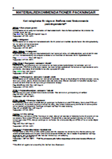
Chemical and physical properties for gaskets
Different gasket material
The table below only gives a rough orientation about the chemical and physical properties of different types of rubber. Many factors affect the lifespan of the rubber, e.g. working temperature, working conditions and rubber compound. In case of doubt, we are happy to provide further information.
| Material | Chemical properties | Physical properies | Operating temperature | |||||
|---|---|---|---|---|---|---|---|---|
| Resistance to | ||||||||
| Weather and ozon |
Water vapor | Strong and oxidizing acids |
Gasoline and oils |
Abrasion resistance |
Breaking point MPa elongation |
Highest °C (dry atposphere) |
Lowest °C | |
| EPDM / ETEN-PROPEN | excellent | excellent | good | bad | good | 7-18 | +140°C | -40°C |
| NBR / Nitrilgummi | less good | less good | less good | good | good | 10-25 | +90°C | -30°C |
| VMQ / Silikongummi | excellent | less good | bad | less good | bad | 4-10 | +200°C | -60°C |
| VITON® FPM/Flourgummi | excellent | excellent | good | excellent | good | 15-20 | +200°C | -20°C |
| PTFE | excellent | excellent | excellent | excellent | excellent | 20-30 | +230°C | -100°C |
| Tuf-steel | excellent | excellent | excellent | excellent | excellent | 270% | +288°C | -198°C |
| Kalrez LS 390 | excellent | excellent | excellent | excellent | excellent | 18.6 | +220°C | -20°C |
Technical information about steel
| EN steel no | SS | ASTM TP | UNS | C | Cr | Ni | Mo | Other | Name | Structure |
|---|---|---|---|---|---|---|---|---|---|---|
| 1.4301 | 2333 | 304 | – | ≤ 0.07 | 17.5-19.5 | 8.0-10.5 | 0 | N ≤ 0.11 | – | Austenitic steel |
| 1.4306 | 2352 | 304L | – | ≤ 0.03 | 18.0-20.0 | 10.0-12.0 | 0 | N ≤ 0.11 | – | Austenitic steel |
| 1.4401 | 2347 | 316 | – | ≤ 0.07 | 16.5-18.5 | 10.0-13.0 | 2.0-2.5 | N ≤ 0.11 | – | Austenitic steel |
| 1.4404 | 2348 | 316L | – | ≤ 0.03 | 16.5-18.5 | 10.0-13.0 | 2.0-2.5 | N ≤ 0.11 | – | Austenitic steel |
| 1.4432 | 2353 | 316L | – | ≤ 0.03 | 16.5-18.5 | 10.5-13.0 | 2.5-3.0 | N ≤ 0.11 | – | Austenitic steel |
| 1.4435 | 2353 | 316L | – | ≤ 0.03 | 17.0-19.0 | 12.5-15.0 | 2.5-3.0 | N ≤ 0.11 | – | Austenitic steel |
| 1.4436 | 2343 | 316 | – | ≤ 0.07 | 16.5-18.5 | 10.5-13.0 | 2.5-3.0 | N ≤ 0.11 | – | Austenitic steel |
| 1.4462 | 2377 | – | – | ≤ 0.03 | 21.0-23.0 | 4.5-6.5 | 2.5-3.5 | N ≤ 0.1-0.22 | – | Austenitic steel |
| 1.4539 | 2562 | 904L | N08904 | ≤ 0.02 | 19.0-21.0 | 24.0-26.0 | 4.0-5.0 | N ≤ 0.5 Cu 1.2-2.0 | 904L | Super austenite |
| 1.4547 | 2378 | – | S3154 | ≤ 0.02 | 19.5-20.5 | 17.5-18.5 | 6.0-7.0 | N, Cu | 254SMO | Super austenite |
| 1.4571 | 2350 | 316Ti | – | ≤ 0.08 | 16.5-18.5 | 15.5-13.5 | 2.0-2.5 | Ti | – | Austenitic steel |
| – | – | – | N08367 | < 0.03 | 20.0-22.0 | 23.5-25.5 | 6.0-7.0 | – | AL-6XN | Super austenite |
| 2.4602* | – | C-22 | N06022 | < 0.01 | 20.0-22.5 | 56 | 12.5-14.5 | – | Hastelloy | Superalloy |
| – | – | C-276 | N10276 | < 0.01 | 14.5-16.5 | 57 | 15.0-17.0 | – | Hastelloy | Superalloy |
Tabel perforated plate
| Diameter in decimales | Diameter in inch | Center type | Hole / square inch | Open surface % |
|---|---|---|---|---|
| 0.033″ | – | 0.055″ straight lines | 330 | 28 |
| 0.045″ | – | 0.066″ straight lines | 225 | 36 |
| 0.062″ | 1/16″ | 0.094″ offset lines | 132 | 41 |
| 0.094″ | 3/32″ | 0.156″ offset lines | 46 | 33 |
| 0.125″ | 1/8″ | 0.187″ offset lines | 33 | 40 |
| 0.187″ | 3/16″ | 0.250″ offset lines | 18 | 50 |
| 0.250″ | 1/4″ | 0.375″ offset lines | 330 | 58 |
Filtering table
| Mesh | Micron | Millimeter | Open surface % | Filter cloth mesh | Filter cloth thickness |
|---|---|---|---|---|---|
| 4×4 | 5156 | 5.156 | 65.9 | – | – |
| 6×6 | 3340 | 3.340 | 62.4 | – | – |
| 8×8 | 2664 | 2.664 | 60.2 | – | – |
| 10×10 | 1905 | 1.905 | 56.3 | – | – |
| 12×12 | 1532 | 1.532 | 52.4 | – | – |
| 14×14 | 1306 | 1.306 | 51.8 | – | – |
| 16×16 | 1130 | 1.130 | 50.7 | – | – |
| 18×18 | 979 | 0.979 | 48.2 | – | – |
| 20×20 | 864 | 0.864 | 46.2 | – | – |
| 24×24 | 703 | 0.703 | 44.1 | – | – |
| 30×30 | 516 | 0.516 | 37.2 | – | – |
| 40×40 | 381 | 0.381 | 36.0 | – | – |
| 50×50 | 318 | 0.318 | 30.3 | – | – |
| 60×60 | 233 | 0.233 | 30.3 | – | – |
| 80×80 | 160 | 0.160 | 31.4 | – | – |
| 100×100 | 140 | 0.140 | 30.3 | – | – |
| 120×120 | 118 | 0.118 | 30.9 | – | – |
| 150×150 | 103 | 0.103 | 37.2 | – | – |
| – | 96 | 0.096 | – | 20×200 | 0.033 |
| 180×180 | 80 | 0.080 | 34.3 | – | – |
| 200×200 | 74 | 0.074 | 33.6 | – | – |
| – | 70 | 0.070 | – | 120×180 | 0.010 |
| – | 65 | 0.065 | – | 120×200 | 0.009 |
| 250×250 | 61 | 0.061 | 36.0 | – | – |
| – | 50 | 0.050 | – | 120×330 | 0.010 |
| 325×325 | 43 | 0.043 | 29.7 | – | – |
| – | 40 | 0.040 | – | 120×400 | 0.009 |
| – | 35 | 0.035 | – | 120×500 | 0.009 |
| – | 30 | 0.030 | – | 120×600 | 0.009 |
| – | 25 | 0.025 | – | 200×600 | 0.006 |
| – | 21 | 0.021 | – | 200×830 | 0.006 |
| – | 10 | 0.010 | – | 200×1150 | 0.006 |
Conversion tables
| Length | |||
|---|---|---|---|
| Millimeter (mm) | Meter (m) | Inch (“) | Foot (ft) |
| 1.0 | 0.001 | 0.0394 | 0.0033 |
| 25.4 | 0.0254 | 1.0 | 0.083 |
| 304.8 | 0.3048 | 12.0 | 1.0 |
| 1000.0 | 1.0 | 39.3699 | 3.28083 |
Exemple: Convert 15 ft to meter (15 ft × 0.3048 = 4.572 m)
| Pressure | ||||
|---|---|---|---|---|
| Bar | Psi | MPa (megapascal) | KPa (kilopascal) | mbar |
| 1.0 | 14.503 | 0.1 | 100.0 | 1 000.0 |
| 10.0 | 145.03 | 1.0 | 1 000.0 | 10 000.0 |
| 0.001 | 0.0145 | 0.0001 | 0.1 | 1.0 |
| 0.069 | 1.0 | 0.006 | 6.9 | 69.0 |
| 0.01 | 0.145 | 0.001 | 1.0 | 10.0 |
Exemple: Convert 15 psi to bar (15 psi × 0.069 = 1.035 bar)
| Volume | |||
|---|---|---|---|
| L | m³ | Gallon UK | Gallon U.S |
| 1.0 | 0.001 | 0.220 | 0.264 |
| 1 000.0 | 1.0 | 219.96 | 264.17 |
| 28.32 | 0.283 | 6.228 | 7.48 |
| 4.546 | 0.0045 | 1.0 | 1.2009 |
| 3.785 | 0.0037 | 0.8326 | 1.0 |
Exemple: Convert 5 gUS to Liter (5 gUS × 3.785 = 18.925 Liter)
| Flow | |||
|---|---|---|---|
| L/min | L/s | m³/h | m³/min |
| 1.0 | 0.0167 | 0.06 | 0.0353 |
| 60.0 | 1.0 | 3.6 | 2.119 |
| 16.667 | 0.2777 | 1.0 | 0.5885 |
| 28.32 | 0.472 | 1.699 | 1.0 |
Exemple: Convert 5 m³/h to Liter/min (5 m³/h × 16.667 = 83.335 L/min)
| Temperature | |
|---|---|
| °C | °F |
| 1.0 | 33.8 |
| -17.2222 | 1.0 |
| -272.15 | -457.87 |
| From | To | Conversion calculation | Exemple |
|---|---|---|---|
| Farenheit | Celcius | °C = (°F-32)/1.8 | (100°F-32)/1.8 = 37.77°C |
| Celcius | Farenheit | °F = (°C×1.8)+32 | (100°C ×1.8)+32 = 212°F |
Pdf about material certificates etc

Pdf about different gasket materials